
Robot 4S-1 a four-servo biped walker |
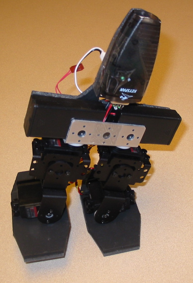
This project is my second attempt at a biped walker (c.f. 3S-1). The leg structure is taken directly from Lynxmotion's BRAT Jr., though I'm using my own feet and other hardware. The controller is a Pololu micro serial servo controller, tethered to a computer via a Keyspan USB-to-serial adapter.
Here are some pictures of the robot (or scroll to the bottom for a video):

Front View |

Back View |
Taking a Step |
Last Thing You See as Your Robot Overlord Expresses Its Displeasure |
Construction: As noted above, 4S-1 is built mainly of Lynxmotion brackets. The feet are made of balsa wood (5 mm thick), glued (with standard Elmer's glue) to black foam rubber, constructed in the following manner:
Note that in my first attempt at this robot, I used rectangular feet, of the same size and shape as the Lynxmotion Robot Feet. But these didn't work nearly as well, especially when the robot attempted to turn, when it would end up stepping on its own toes or heels. The stretched-octagon shape used in the final design worked a lot better (and was, coincidentally, a lot cheaper too).
In addition to the feet, everything above the brushed-aluminum "U" channel is custom too. The back is made of black foam board (not to be confused with foam rubber -- foam board is light but stiff). The "arms" are battery cases, each containing two AA cells. The "head" of the robot is the Keyspan USA-19HS USB/serial adapter. The battery boxes, combined with the foam board, just fit tightly in the aluminum U-channel. So, that's what holds the robot's upper body onto the hips; I just squeeze these parts in, and they stay there nicely until I pull them out again.
Note that the 9V battery taped to the back was not in the original design, but proved necessary when I found that I couldn't reliably power the controller board from the same batteries as the servos.
Electronics: The Keyspan USB/serial adapter is connected to a custom connector, made by soldering some wires and jumpers onto a standard DB-9 connector. This is attached (via a Molex KK female connector) to the Pololu micro serial servo controller. The controller board is mounted to the foam board with a couple of tapping screws. That board also gets power from a 9V battery, and servo power from the four AA cells.
Each of the two 2-cell battery packs is terminated in a Molex KK connector (a standard I try to always follow). So to combine them into a 4-cell pack, I taped the two connectors together, put a jumper wire between them (from the + side of one to the - side of the other), and brought the outer two holes out into a third connector, which went onto the controller board. You can see this in the back view (though note that the battery connectors are not actually plugged into the controller board in these pictures).
Programming: I controlled the robot with a couple of little applications written in REALbasic. One let me build and save poses and short sequences of poses. The other implemented a state machine: it kept track of what position the robot was in (or would be in at the end of the current sequence), and where the user wanted it to go (as indicated by a press of an arrow key). Based on these, it would select the appropriate sequence to execute next. It worked very well, though the coding was a bit onerous, and in the future I'll probably try to think of a way to streamline it.
Results: This walker performed very well. At the December Front Range Robotics Club meeting, I did a "kick the cups" competition with this robot, and it knocked over every cup in reasonable time without falling off the table. (My robot was the only competitor, so it won by default!)
The custom feet worked out really well, as did the foam board/battery combination wedged into the U-channel. The programming approach also performed well, but could use some refinement and polish.
My main regret with this robot is the tethered connection. Having a cable coming off your robot's head is a bit uncouth, and if you don't keep it right above the robot, it can throw off its balance a bit too. You can see this in the video below; at some points I wasn't holding the cable properly and it started limping to one side. I still consider myself a newbie to robotics, and wireless control seems like big magic to me. But it's high on my list of things to add to my next biped.
The other problem with this design is that I highly doubt that it's even possible for it to get up from a prone position. There are other four-servo designs out there that can do this. However, I may simply add some additional degrees of freedom in the future, which would make solving that problem much easier.