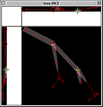
The format is a combination of TEXT and PICS: the tracing data is stored as text in the data fork, and the image data is saved in PICS format in the resource fork. You should therefore be able to open the file in a text or image-processing application. (See also Preferences, below.
Note: Since neither QD3D nor VRML currently supports a tapered cylinder, straight cylinders are used whose radius is the average of the radius at each endpoint.
In a rendering window, Copy puts the current render image on the clipboard in PICT format. You should be able to paste this into any MacOS graphics application.

For all three views, the slice displayed is the one that corresponds to the cursor position. The cursor is a crosshairs shown in all three views. It is moved by clicking the mouse in any of the three. When the X position of the cursor changes, a different slice will be displayed in the Y-Z view. When the Y position is changed, a new X-Z view is displayed; and when the Z position is changed, the main (X-Y) subpane is updated. You can quickly explore your volume in this way.
You may also nudge the cursor using the keyboard. The arrow keys move the cursor in X and Y, as do the numbers 4, 6, 8, and 2 on the numeric keypad; - and + (minus and plus) move the cursor in Z.
To place a node, first move the cursor to the center of the node. Check all three views to make sure you've centered it in all three dimensions. Then hold the shift key, click again, and drag the circle so that it just fills the dendrite in three dimensions. (Actually, the node is a sphere; thus it appears round in all three views.) Unless it is the first node you've placed, it will be connected to the previously selected node. The new node will become the currently selected node, ready to be connected to the next. If you need to adjust the node diameter, hold the shift key and use the arrow keys (or the numeric keypad).
To select an existing node, just click near its center. Remember that this may take two clicks, since you have to properly locate it in three dimensions. The selected node is shown in green, whereas all other nodes are red. As described above, the currently selected node will be connected to any newly created node. You can also delete this node by pressing the [delete] or [del] key.
To move the currently selected node, hold the option key, grab the node with the mouse, and drag it to a new position. You may also hold the option key down, and nudge the node with the arrow keys or numeric keypad.

At the top of the window are rotation speed controls and indicators, one each for the X, Y, and Z axes. Red meters between each set of buttons indicate the speed and direction of rotation around that axis. By clicking the left and right buttons, you can change the speed. You can also stop rotation on an axis by clicking between the buttons (i.e., on the label or on the speed indicator).
You can leave the rotation window up and spinning while you return to the tracing window for more work. It will continue to spin, though there may be pauses while the application is processing more important work. Changes in the tracings will be reflected immediately if the rendering is spinning in at least one axis.