
Joe's Robot Log a chronicle of mechanistic machinations |
This page presents a brief chronological log of my robotics efforts. Feel free to contact me with comments or questions.
- Joe Strout
First Critter Crunch Entry | Oct. 25, 2009 |
Today I fielded my first entry in the MileHiCon's Critter Crunch contest. My little remote-controlled (via Bluetooth) scratch-built vehicle didn't fare well in the competition, but all systems functioned flawlessly and the whole experience was both educational and fun. Most important lessons learned: speed is crucial; keep the weight over the wheels; have a good scoop on front; and speed is crucial. (Yes, that bears mentioning twice!)
Click the photo at right to read a more detailed report.
Cylon-inspired RoboBuilder takes shape | Mar. 8, 2009 |
 Sheesh, has it been over a year since my last log entry? I'm terrible at keeping up logs, but I haven't been completely idle. Progress has been fairly steady on our "Bot50", about which I will hopefully write more later. But today I want to instead present my Cylon-inspired RoboBuilder mod (right; click for larger image).
This began as a stock RoboBuilder kit, with the addition of a 3-axis accelerometer and bluetooth module. But those are internal; I also wanted some way to distinguish my bot from other RoboBuilders on the outside. So I took apart the head, which includes a translucent section intended for IR control and distance sensing, and inserted a set of 5 small, bright LEDs controlled by a tinyCylon chip. I put the chip in a socket soldered directly to the prototyping area that the RoboBuilder head already contained (you gotta love the RoboBuilder engineers!). The LEDs are set into a strip of black plastic hacked from a CD case insert. The whole circuit draws power from the same 5V regulated supply used for the IR receiver.
Then, I ordered a set of clear plastic body shells (and an extra head) from Trossen Robotics, and spray-painted them metallic silver (several coats with buffing in between). A quick swap for the old parts, and the result is at right.
Of course a static picture doesn't do it justice, so if you can, come to RoboGames 2009, where I hope to have this guy (who still needs a name!) ready for competition. (Discuss here or here.)
FCRFFC is a success! | Mar. 10, 2008 |
My own demo bot "Sponginator" successfully put the candle out in 2 of 3 tries, with a total score of 72.12. The one failure was a sensor problem: the candle was about in the middle of the large room (the "kitchen"), and Sponginator stopped in the doorway, looked around, and entirely failed to see it. More careful calibration of the IR sensor may have helped.
For more details and pictures of the event, go to http://www.strout.net/fcrffc/2008.html.
HiTechnic board fails, but Sponginator forges on | Feb. 24, 2008 |
 I had high hopes for that HiTechnic board (see my last entry, below), but in practice, couldn't get it to work out. There are fine analog input channels, A0 through A4. A0 works as I would expect: when I connect it to +3V or GND, the corresponding value read from the NXC code goes high or low as I would expect. But channels A1 through A4 do not; their values don't change based on what I connect them to. I was using test code straight from HiTechnic, and double-checked it myself against their docs, and it all looks correct to me. I wrote to them about it, and they generously offered to replace the board (and to do so quickly, since I told them about the upcoming contest). But the second board behaved exactly the same way. HiTechnic got back to me about a week later and said that the board worked fine for them, and basically they had no idea why they're not working for me.
So, I had to give up on that board, but fortunately, Extreme NXT came to the rescue! It turns out that chapter 8 of this wonderful book actually discusses the Sharp analog distance sensors specifically, and provides a "transistor buffer" circuit (see their Figure 8-7) that lets you drive such a sensor directly from the sensor port, and read it on the NXT as a reflected light sensor. I made up a couple of these circuits on perfboard, only slightly embellished with a couple of capacitors to dampen down the noise these sensors generate.
The first of my circuits worked like a charm. The second one did not; it sort-of worked, but had about a 1.6V bias that greatly limited the range of distances it would report, even using the very same sensor. I scratched my head on this for quite a while, because I was laboring under the mistaken belief that all the transistors in my freshly opened Radio Shack transistor pack were actually what the package claimed them to be. But they were not; in fact, neither of them were the 2N3906 that they were supposed to be, but one of them happened to be close enough, and the other was quite different. That'll teach me to trust Radio Shack.
But upon reflection, I realized that one good circuit is all I can use anyway. The big drawback to accessing my distance sensors this way, instead of through the HiTechnic board, is that they take up a sensor port each, and the NXT only has four sensor ports total. I need at least a flame sensor, a line sensor, and I really wanted that front bumper. That leaves me room for only a single distance sensor. So that's what I've got, as you can see in the front and side views of the current bot, which I've dubbed "Sponginator". The flame sensor is peeking out through the sponge arm; the distance sensor is mounted on the right side, forward of center; the line sensor is hidden underneath; and the front bumper is obvious.
A busy night of programming before our last FRRC meeting got Sponginator wandering around the fire-fighting arena, and peeking into each room, with fairly decent reliability. The hardest one is of course the floating room in the middle; this is where I really wish I had a couple more sensors. I'm currently relying on dead reckoning for that one, and even with the NXT motor encoders, it only works about half the time.
But I'm very pleased to say, the local robot hobbyists are stepping up to the challenge, with a good half-dozen registered participants already. I think it's going to be a fun and inspirational event.
HiTechnic NXT interface board | Jan. 04, 2008 |
 Today I received a HiTechnic "NXT Prototype Sensor Board". This is really an interface board; it handles all the I2C communications with the NXT, and provides six analog (10-bit) inputs, as well as six digital input/output lines. It also provides four different power supplies, and of course ground. (Click the thumbnail at right for a bigger picture.)
I ordered the "solderable" version (model NPT-1050), mainly because it's ten bucks cheaper than the "solderless" one ($30 instead of $40). It comes with a big prototyping area next to the circuitry, and no headers installed. But I can't possibly know what electronics I'll want to attach to these I/O pins, beyond perhaps some very generic indicators (like LEDs on the digital lines). So I promptly soldered female headers onto all 16 I/Os. This will let me insert breadboard wire for prototyping, and when I get a serious application, I can make up a connection cable using a male header, so that the app-specific electronics are on a separate daughter board. This way, I can continue using the HiTechnic interface board on any number of different projects, just by plugging in a different daughter board.
Fire-fighting bot gets an eye and an arm | Jan. 01, 2008 |
 The FRR club meeting coming up tomorrow has spurred me to add an arm to my fire-fighting robot. Like my first firebot, the arm here is designed to extinguish a candle by snuffing it with a wet sponge. But unlike that bot, I decided to use a parallel motion linkage on the arm, to keep the sponge horizontal in any position. This (barely) keeps the arm from exceeding the height limit when in its retracted position, and I think should do an even better job of extinguishing the flame.
You can click the image at right for a closer look; I also have side views with the arm extended or retracted.
At the same time, I also mounted the IR flame sensor, behind the arm and peeking out right through the gap in the arm bars. You can see it in this front view; it's the modified gray 2x4 brick visible right under the sponge.
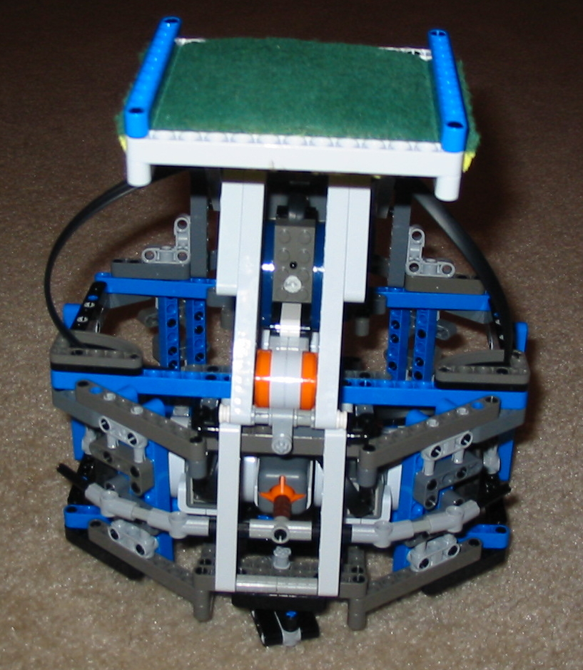
More progress on new fire-fighting bot | Dec. 16, 2007 |
 I've made more progress on the new fire-fighting robot. You can see an angled front view at right (click the thumbnail to enlarge). It's basically a second octagonal deck mounted above the first, with the NXT mounted on the back at a comfortable angle, and a bumper on front connected to a standard NXT touch sensor. Note too that I've chosen the heavy part of the motors as the front of the bot; their weight is more than offset by the NXT (which includes the batteries), and while I do want to have most of the weight in the back, there's no sense unbalancing it too much.
Hooking up the NXT has of course allowed me to test the drive system. It does very well with both straight lines and turns. I haven't actually measured its speed, but I would characterize it as "zippy" -- plenty fast enough for contest purposes.
The next step, after some additional programming tests, will be to mount the IR sensor and design a sponge arm. And this time, I'm going to make sure that when the arm is "at rest" it is tipped back over the robot, so I don't have to work so hard keeping the arm up while the robot drives around.
A new Fire-Fighting robot base | Dec. 12, 2007 |
 Last night I built a new base for a fire fighting robot, based on ideas and experience gleaned from last weekend's demo. I'm very pleased with how it turned out. Click the thumbnail at right for a larger picture.
This base is octagonal, which should help it avoid getting caught on walls and corners. Each wheel is supported on both sides, so they can support a lot of weight. There are two casters, front and back, so it's very stable in any direction and won't tip over. I'm also using larger, thinner tires, and a wider wheel base, which should improve speed and maneuverability. Finally, the motors are connected to the wheels via two differently-sized gears, allowing me to select between two gear ratios just by swapping the gears.
My plan is to build up the sides of this base slightly higher than the wheels and motors, and make it a self-contained module. Then, I'll build a top module with the same octagonal shape, and snap it onto the base. The idea is that, once I have a good base design, I should be able to reuse it for different tasks (e.g. can-grabbing or fire-fighting) by replacing only the top module.
Robot Fire-Fighting Demo | Dec. 08, 2007 |
 Today we held a demo at the Discovery Science Center to promote the Fort Collins Robot Fire Fighting Contest. Click the picture at right to see the bot I brought. It used three sensors: a Techno-Stuff IR Flame Sensor (which also did a great job finding the 15W black light bulb for the "Robot Hide & Seek" event), a downward-facing visible light sensor to detect floor markings, and another light sensor angled ahead and to the side for wall tracking. It used a wet sponge on an arm to extinguish the candle, and could make multiple attempts if the first try didn't hit the target. It was able to follow the wall fairly reliably, as well as find and extinguish a candle in whatever room you put it in. These were separate programs, however, so the robot was not yet able to do the whole event.
I tried to take some video but, for reasons I haven't figured out yet, the video didn't turn out. So we'll have to content ourselves with the photo above, and take my word for it.
I did notice one problem with this robot design: when the arm missed the candle (which seemed to happen in some rooms more than others), the weight and momentum of the arm would actually tip up the back of the robot. It also tended to scoot it a little back and to one side or the other, messing up its aim for subsequent attempts. This experience, along with all those videos of successful robots (which we showed during the demo on a projection screen), have given me much food for thought.
Summary of my long hiatus | Nov. 26, 2007 |
First, the 8-servo biped described in the previous entry just didn't work out. I worked for quite a while trying to find a movement sequence that would enable it to stand up from a prone or supine position, but without success. It seemed to be too top-heavy, and even when doing the splits, just couldn't get its weight over its feet. Perhaps its arms were too short, but the arms were pretty long already; any longer would have started to look silly. It could walk nicely, but I really think a biped should be able to get up on its own. So, I finally gave up on that one, and concluded that low-DOF robots (this one had only 2 DOF per leg) that actually work robustly are engineering marvels, beyond my current abilities. In addition, the head proved to be a major nuisance.
So, just recently, I've torn that robot apart and started a completely new biped, with 4 DOF per leg. So far I have the legs built and attached together at the hips, and I'm pleased with the way they are able to move. I still nead to build the upper body, including arms, which will require buying some additional servos and brackets (as well as another servo controller). I'm hopeful that the extra degrees of freedom will greatly simplify such Herculean tasks as getting up after falling down. But I'm also a bit worried that such a large bot (it'll be roughly Robo-One size) will require much stronger servos than I'm willing to buy. We shall see, and I'll try to get some photos up soon.
Meanwhile, most of my robot time has been spent preparing the local (Fort Collins, CO) demo of the Trinity College Robot Fire Fighting contest. This is going to be held at the Discovery Science Center on December 8th. I've built an arena (with a nifty modular design that makes it easily storable and transportable), though I still have some decorating to do. I've also made a good start on my own fire fighting robot. It's a LEGO NXT robot that uses a techno-stuff IR sensor to detect the flame, and a wet sponge to put it out. Photos of all this should be coming soon, too.
More progress on 8-DOF biped | Mar. 21, 2007 |
 I've made quite a bit of progress on the new biped. Some of this is just cosmetic, like the gold model paint on the hand balls (Model Masters, applied to the inside), which will eventually adorn the head too. But more importantly, I mounted a battery box on back (using two gusseted plastic angle brackets), a DPST switch on the shoulder to control power to the servos and electronics, and oh yes -- actual electronics in the head. This currently consists of just the Pololu servo controller, plus a 9V battery and a prototyping breadboard that is currently used only to connect power and switches to the electronics. Eventually I expect to add a Coridium ARMexpress controller here, though once the circuit has stabilized I'll probably replace the breadboard with a soldered circuit board.
Just this evening, I finally managed to get everything hooked up and crammed back into the head, including the serial connection to the servo controller, and verified movement of each servo. This is real progress; now I can focus more on movement and programming. There are still a few hardware issues to resolve, in particular, you may notice that the head is drooping. The "neck" area is so inaccessible that I couldn't get a nut onto the bolt that's supposed to hold the head in place. I'll have to rethink that attachment; I want something that will hold the head firmly yet not be too onerous to take on or off, since I need to open the head up every time I mess with the electronics (or replace the 9V battery).
Meanwhile, here are the front and back views of the robot in its current state.
My biped gets some balls | Feb. 02, 2007 |
 The new biped is shaping up. I ordered several "clear plastic acryllic fillable ball ornaments" (100 mm and 60 mm) from Factory Direct Craft Supply. (One of the 100 mm balls arrived cracked; I called them up, and they sent out a replacement right away, no questions asked -- even though the shipping must cost them several times more than the item!) These I've attached to the robot, along with the feet from 4-Servo Biped. I used my new Dremel tool to cut a slot into one hemisphere, and fed all the servo wires into it. This makes them nice and neat, assuming you don't look inside the ball.
I'll soon paint the ball (from the inside) so that this isn't an issue, but I haven't quite settled on what I want it to look like, nor what I'll call this robot. I'm thinking of painting the head bright yellow with black eyes and smile, and calling it (predictably) "Smiley." But we'll see. Again, click the small image at right for a larger view.
A new biped | Jan. 21, 2007 |
This robot is inspired by the cute little ball-headed robot in this video, and also seen in this photo. It's an adorable little robot that is small, but surprizingly agile, and I want to see if I can do something similar.
This project doesn't have its own page yet, so in the meantime, click the small image at right for a closer view.
RB-1 Gets a Torso | Jan. 14, 2007 |
 I've made significant progress on my RB-1 robot. It now has a torso composed of two large plastic coffee cans, plus two platforms. This fabrication work is going a lot faster than ever before, because I used some Christmas money from relatives to buy myself a Dremel tool. I don't know how I survived so long without one! I'm still getting the hang of it, but it's already saved me countless hours and enabled me to do things I simply couldn't do otherwise (those coffee cans are surprisingly tough!).
Motor Controller Carrier Board | Dec. 15, 2006 |
 We need to use the Pololu Micro Dual Serial Motor Controller (about which I previously wrote a tutorial) for our new
RB-1 project. I had originally planned to put it on a solderless breadboard, but Radio Shack was all out of the little ones, and I got impatient waiting for my order to arrive from Mouser.
We need to use the Pololu Micro Dual Serial Motor Controller (about which I previously wrote a tutorial) for our new
RB-1 project. I had originally planned to put it on a solderless breadboard, but Radio Shack was all out of the little ones, and I got impatient waiting for my order to arrive from Mouser.
So, I decided instead to make a carrier board. (Click the image at right for a closer view.) I used a low-profile 18-pin IC socket to hold the Pololu SMC. Each of the five white blocks shown is a male polarized Molex KK header. The two at the top are for motor power (left) and electronics power (right). The middle two are the left and right motor outputs. The one at the bottom is for RS232-level serial input. The two bus lines down the center carry ground (left) and electronics voltage (right). The red wires carry motor voltage, and the green wires are of course negative motor voltage.
The two resistors and transistor at the bottom convert the the RS232 input into the logic-level serial required by the SMC. This lets me directly connect in the simple DB9-to-KK connector I'd already made for my 4S-1 robot. Someday, I may need a logic-level connector as well, if I'm using a robot controller for the brain instead of a laptop, but the RS232 input is fine for now.
I've tested the board, and it works like a charm! I just hook up the batteries, motors, and serial cable, and it's ready to go. (I know, it's a very simple thing, but it's the first circuit board I've ever made from scratch, so I'm very happy that it works so well.)
New project: RB-1 | Dec. 14, 2006 |
 I've started a new project, a laptop bot based on a RAD Robot (an old toy sold, I think, by Radio Shack in the late 90s). We got the robot from an eBay seller last week, and so far, we've opened it up, verified that the motors work, and worked out how to mount a platform and laptop to it. We're calling this robot "RB-1" for "RAD Base, version 1".
4S-1 Completed | Dec. 12, 2006 |
AVR Butterfly | Nov. 19, 2006 |
 A friend (and local robotics guru) kindly gave me an AVR Butterfly board a while back. This is an evaluation board for the Atmel AVR chip, and it's also a really great unit in itself. It comes all set up with a multi-line text LCD display, a 5-way joystick, several sensors, and a coin battery right on the board. It comes with a pretty sophisticated program pre-installed in the firmware, so you can start playing with it right away. It even has a bootloader, so you can program it with no special hardware beyond a serial adapter. To take it further, all you have to do is solder on some header pins and figure out the software you need on the desktop computer. It looks like with the right software, it could make a fine little robot controller all by itself.
So, I'm finally starting to figure this out. I'm using a Mac, and of course all of Atmel's desktop software is for Windows, but there is an extensive open-source community using AVR chips. I've learned that a program called AVRDUDE can, among other things, send files to the bootloader, as described here.
When I get this all figured out, I'll try to write up a tutorial for other Mac users to follow.
Pololu Serial Controller Update | Nov. 18, 2006 |
Robot 4S-1 (update) | Nov. 12, 2006 |
However, early experiments with this turned up a problem with 4S-1, and it wasn't in the sequencer software. Moving certain servos would cause strange behavior in other servos, and this would persist until the controller board were reset. I posted about it in the Pololu robotics forum, but got no reply (which is disappointing; Pololu has always been responsive in the past). After some experimentation, I concluded that some of the beefier servos (like the HS-545) were causing such a current draw from the shared batteries that the controller board to essentially suffer a brown-out.
This was fairly easily solved by powering the board from a separate 9V battery. I don't like it asthetically — 4S-1 now has a 9V battery taped to its back — but it has certainly fixed the strange behavior.
Robot 4S-1 (in progress) | Nov. 07, 2006 |
Giant House Eyes | Nov. 03, 2006 |
 For Halloween, we turned a couple of upstairs windows into a pair of giant eyes. The eyes move — and not just slowly back and forth, like one of those store-window displays. These eyes move quickly to a position, then pause, and then move quickly to some other position, just like real eyes. The effect is cute and a bit creepy at the same time, as the house appears to look up and down the street. See how we did it.
Robot 3S-1 (alpha 1) | Oct. 31, 2006 |
Cheap Servo Alternative | Sep. 22, 2006 |
Tamiya Dual Gearbox and Casters | Sep. 21, 2006 |
 Wow, it's been a long time since my last entry, but I haven't been completely idle — in fact I have a number of irons in the fire. One is a base module, based around the Tamiya Double Gearbox and Ball Caster. And actually, I got a set of Tamiya wheels while I was at it, too. As usual, Pololu has good prices on this gear.
In brief, I've been delighted with every Tamiya kit I've tried so far. This is not toy stuff — it's serious hardware, highly configurable and yet easy to assemble. I hope to have pictures of my robot base posted soon.
ETH32 Received | Dec. 15, 2005 |
I received my ETH32 unit and preliminary documentation yesterday, but unfortunately I'm going out of town for two weeks' vacation. So, excited though I am, it'll have to wait until January or so before I can dig into it.
Pololu Motor Controller Tutororial | Dec. 08, 2005 |
Pololu Micro Dual Serial Motor Controller | Nov. 21, 2005 |
OWI Robotic Arm Kit | Nov. 18, 2005 |